Projects
This page will collect some info about various projects (software, hardware, or other creative) that I waste some of my time with. Most should be fairly recent, but I'll try to eventually also put up some info about long-ago projects.SIDshield for Arduino
If, like me, you grew up with a home computer of the 8-bit age, you will be familliar with the sound of the Commodore 64, generated by the famous 6581 SID chip. I decided I wanted to hook the 6581 from my original C64 to an Arduino. This is the result.
Project Files
(I now put progress info of my projects on my blog, so for this see the entries here, here, and here.)Simple VHDL SPI interface (slave)
To further get some practice in VHDL and to allow me to interface complex devices on an FPGA, I want to be communicate with my Arduino in a simple way. SPI seems to be the way to go, so I wrote myself some code to implement a simple SPI interface, for CPHA=1 (mode 1 or 3). Using CPHA=1 means that the data lines do not need to be set before the first SCLK transtion.
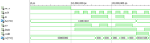
The VHDL code is here, and a simple (non-comprehensive) test here. The interface has not yet been tested in a real implementation, but does synthesize. The simulation waveforms are here.
The interface should be simple to use and understand: If "valid" goes high, data can be read from Rx. If "busy" is low, Tx can be modified. Watch the "valid" line to make sure the data got transmitted. If SS goes high while SCLK is active (high in my implementation, CPOL=0) or the byte boundaries are not respected, things can be unpredictable (but internally the interface goes back to idle).
I'm putting the code out here with a
 Creative Commons Attribution 2.5 Canada License.
STM Bus Info on Java-enabled Phones
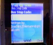
Montreal's Bus and Metro corp (the STM) provides a neat feature where you can go to their website, type in the 5-digit code of a bus stop, and get the times of the next few buses that (should) show up. It's useful, and actually integrated into Google Maps, if you zoom in far enough and click on the blue bus symbol.
That info is much more useful when out and about, of course. There are a few options out there, most notably an iPhone app "STM mobile", see a summary here. However, I don't have an iPhone, no data plan (poor starving student!) so I wanted something using the minimal amount of data. Fido still charges $0.05/kB (on prepaid voice) so downloading the whole page from the STM (about 40kB!) is not a good idea.
So, I use a two-step approach: My phone sends the 5-digit code to my server at home, which uses an updated version of the code below (see "Reading bus info from the STM website") to look up the stop info, and then just sends the textual data back to the phone, which displays just that. Total amount of data transferred is less than 1kB, so it'll only cost $0.05 per use. The data transferred on my home server is negligible in in comparison to my regular DSL traffic. Even the load on the server is not even worth considering (unless suddenly everyone starts using it... but I think it could handle dozens of queries per minute).
The JAVA code is very unpolished! Since I'm busy with Real Life (academic) stuff I can't work on the code at this time. This is the first Java J2MEE code I've ever written, it's very rough - doesn't even quit properly! I'd like to implement many features (such as recalling the last lookup, a "favourites" list, etc, etc... The server address (my home server) is hardcoded in, that should be user changeable! Since it's my home server, I can't guarantee uptime for anyone but myself (sponsors or commercial backing would be welcome!)
Code and Binaries
- The Java J2MEE app: jar, jad. It's only been tested on my own Nokia 5200. JMMV.
- Source code: STMBus.java, busStopSender.java.
- The code on the server is here. Requires Python, Beautiful Soup, and Twisted.
If you have some other mobile device: If you have some form of telnet on your device, just telnet to port 3480 on fornost.dyndns.org and send the 5-digit code. You'll get the timetable info. That's all the Java code does, anyways.
I wrote this mostly around April 2009.
Reading bus info from the STM website
I have written a small script in Python to quickly get the info on the next few coming buses given the 5-digit bus stop code. This is only for the Montreal STM of course!
This code uses Beautiful Soup, a really nice HTML parsing library.
Example use:
$ ./scrapeSTM.py 50111
129 North
19h00 19h18 19h36 20h01 20h31 21h01
535 East
18h56
80 North
18h57 19h01 19h06 19h11 19h17 19h22
365 North
01h46 02h26 03h06 03h46 04h26 05h06
Testing a Li-ion Battery using an Arduino
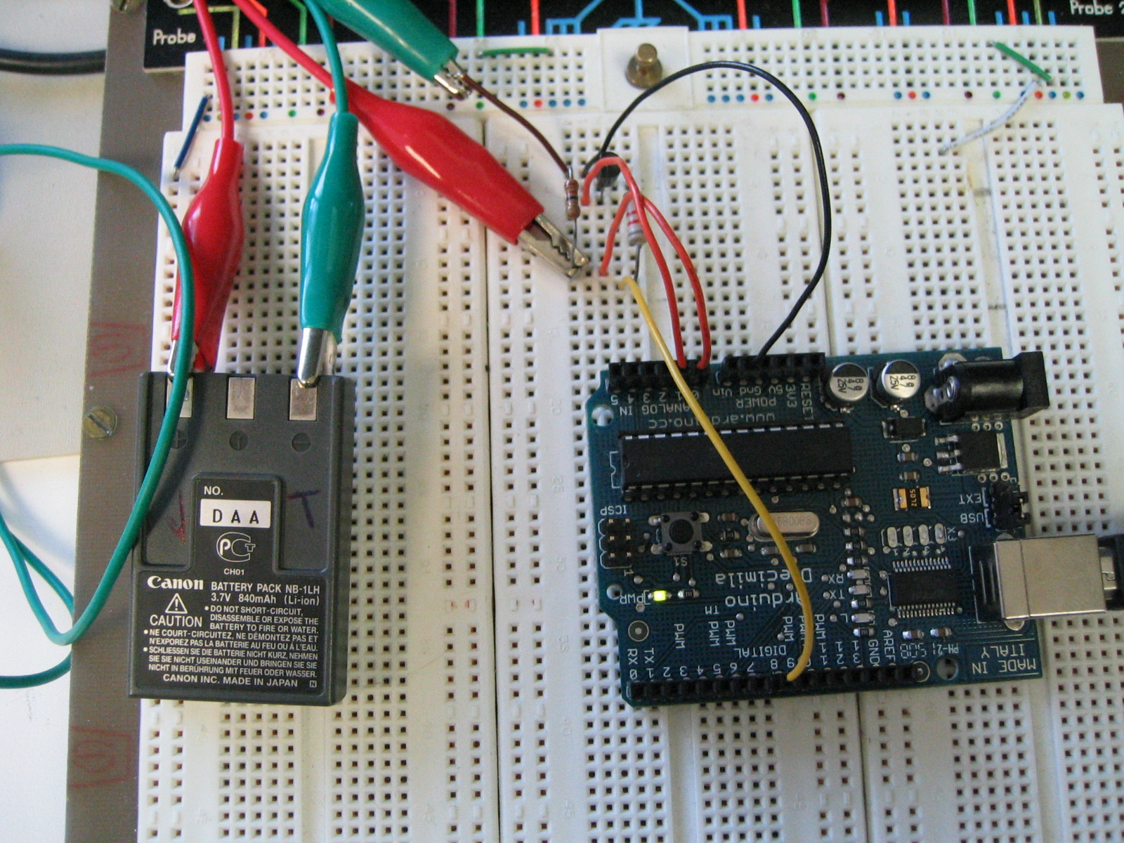
The problem was the following: My camera (Canon PowerShot S230, about 7 years old) was behaving badly on my skiing vacation. One or two shots, and it would turn off due to low battery warning. So I asked the question: just how much do those batteries (bought along with the camera in 2001) still hold their charge? A small circuit and my Arduino board can answer that question!
Parts
- Arduino Diecimila
- One NPN transistor (from my junk box, I measured a common-emitter gain of about 115)
- One 22 Ohm resistor and one 3.3k Ohm resistor. That's what I had handy in the right ballpark.
- A breadboard!
- This sketch on the Arduino
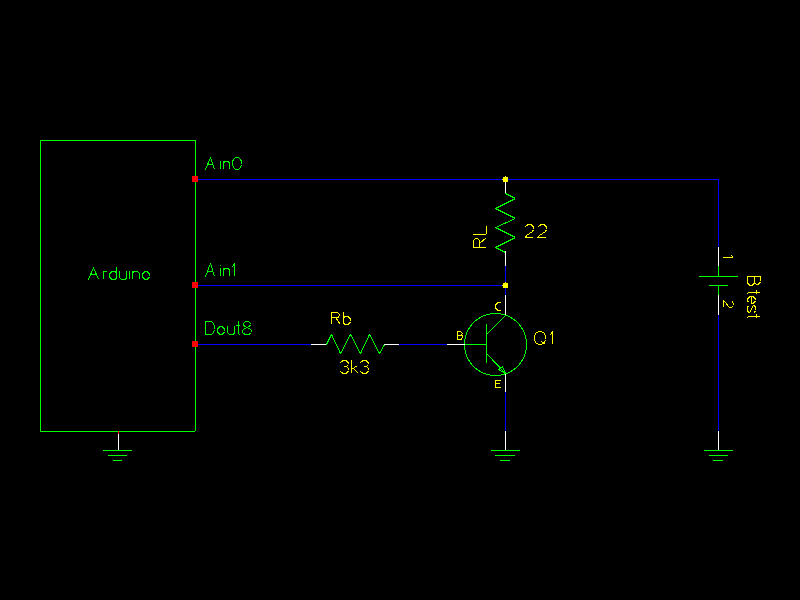
- The schematic.
Notes
The circuit is pretty simple. The resistor between Digital pin 8 and the
base of the transistor causes a current of (5-0.7)/3300 = ~1.3mA, which the
transistor in linear mode amplifies to about 150mA collector to emitter.
The load resistor of 22 Ohms takes some of the heat off the transistor
and allows me to measure the current to boot (actual current turned out to be
about 128mA).
The code on the Arduino starts in idle state, with the transistor off. If
the ASCII char 'F' is received, it switches into fast discharge mode, turning
the transistor on, and measuring the voltage of the battery (Vbatt) and
between the load resistor and the transistor (Vl). The current can then be
calculated using (Vbatt-Vl)/22. Every half-second, Vbatt and Vl are sent out
on the serial line (in mV), along with the time (in milliseconds) since the discharge
process was started. The format of the line sent is "time state Vbatt Vl" (state is for
debugging).
There is also a slow-discharge mode, which will turn the transistor on for one minute,
then turn it off for another.
Either mode will return to idle (transistor off) once the measured battery
voltage is less than 3.2V.
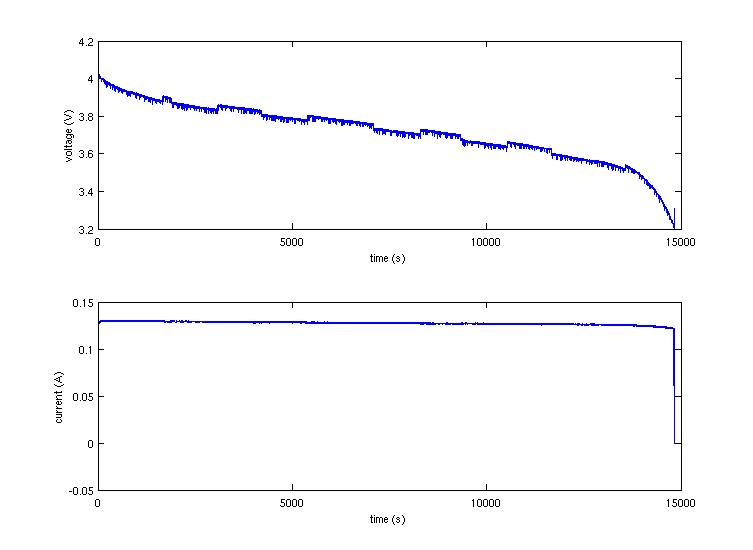 Click on the graph to see a test run with a battery rated 850mAh. Without
needing to do integration, we can tell that at a constant drain of 128mA,
the battery lasted about 15000s, or about 4.2 hours, so its capacity is now
about 537mAh.
Click on the graph to see a test run with a battery rated 850mAh. Without
needing to do integration, we can tell that at a constant drain of 128mA,
the battery lasted about 15000s, or about 4.2 hours, so its capacity is now
about 537mAh.
I don't know what causes the funny jumps in voltage (~0.02V); it doesn't matter
really either since the current remains constant.
Project completed February 27, 2009.
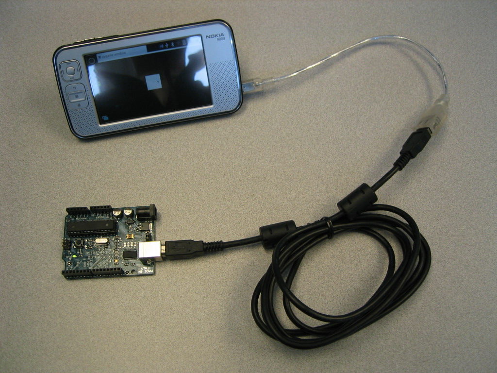
Nokia N800 controlling a Arduino Diecimila over USB with Python
This project was also a small hack just to teach me a few things: Getting code to run on the N800, Python, pygame, and Arduino hacking. I chose pygame because in the future I want to have a nicer nonstandard UI and since I don't like flash like these guys, I looked at SDL and then pygame (the Python hooks into SDL). I also dislike the serial-on-network port proxy business, and go directly to the serial port using pyserial.
Parts
- The Arduino Diecimila, the USB version of the Arduino
- A Nokia N800 or N810 with the latest OS, and the kernel patched to include a driver for the USB-to-Serial chip on the Arduino. You can compile this yourself easily enough with the Maemo Scratchbox environment (see the documentation on rebuilding the kernel). Or you can download the one I built here, but I don't know if it'll work on the N810. See also a guide on how to flash the kernel. To recompile the kernel, here is my config file. The only changes are enabling the FTDI driver and disabling the USB whitelist (so that I can use hubs).
- A USB OTG cable, or any appropriate cable to connect the above to the N800/N810. If not an autoswitching OTG cable, you need to have a method to switch the N800 into USB Host mode, look for the USB control package in the Application manager.
- pyserial. There is no easy-to-install package for this yet, but just go to the pyserial website, download the tar.gz file and then move the "serial" directory into /usr/lib/python2.5/site-packages/.
- The code. (This is the code running on the N800)
- On the Arduino, this code is running.
Notes
That was easy - well, aside from the setting up scratchbox for the first time, compiling the kernel, figuring where to put pyserial, reading up on pygame... The actual writing of code was a mere few minutes!
All of this happened early February 2009.
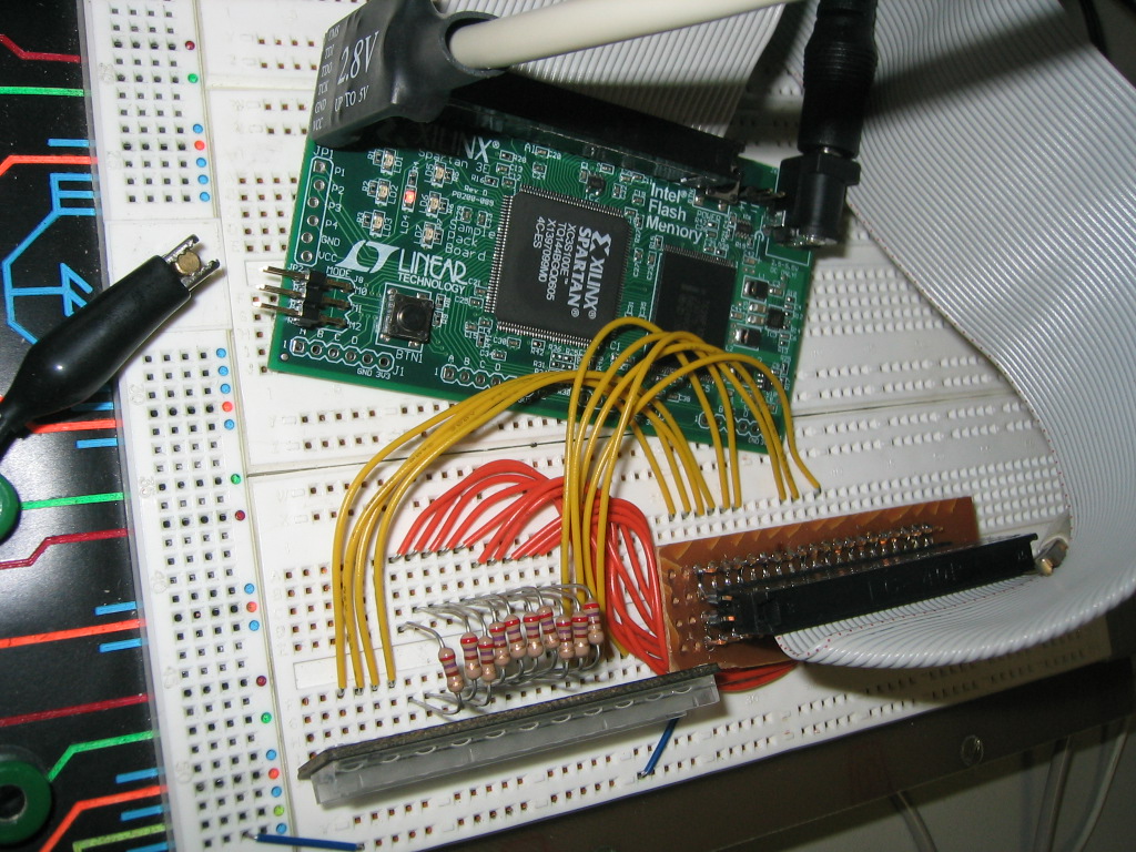
FPGA driving HP LED display
The purpose of this project was to teach myself about FPGA's, VHDL, and such things, since most of my hardware to date had been done with discrete "74LS" TTL or 4000 series CMOS chips, as well as 8-bit CPU's (perhaps I'll post my 68HC11 and PIC designs that I did for UPMACS around 97/98). Since I got a free Xilinx Spartan-3E "Sample Kit" at a small SYTACom conference a while back, I decided to play around with it.
Parts
- Xilinx Spartan-3E "Sample Kit" with a Spartan-3E XC3S100-TQ144 FPGA (manual)
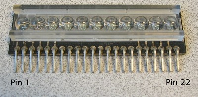
- LED display module from a (broken) HP-34C calculator (1990-0657) (pic)
- Solderless breadboard and wires
- Generic PC with windows and Xilinx WebISE
All work on the project was in Fall 2008, ended Dec. 12 2008. Files are here.
Notes
I managed to do what I set out to do -just play with FPGA development
a bit. This design is not usable if I wanted to drive the LED display
any practical purpose though; the LEDs are far too dim and vary brightness
based on how many segments are active. A proper implementation would
be using real LED drivers - though even simple transistors in linear mode
(thus constant current) on each segment line would do.
Curiously, I had to juggle pin assignments a bit - WebISE would spit out
errors when I tried using certain pins (128 and 129, IIRC) even though
the manual claimed them to be available for general-purpose single-ended
I/O.
Now, off to use the FPGA for actual useful circuits!